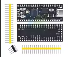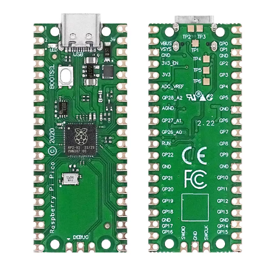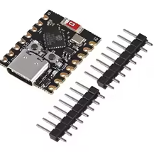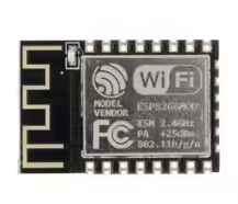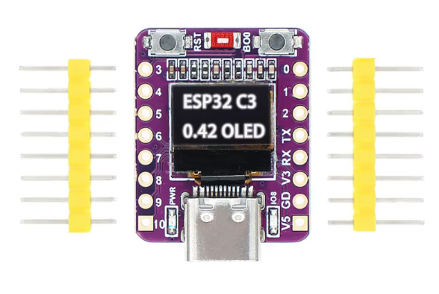
ESP32-C3 OLED development board with 0.42 inch OLED module ceramic antenna wifi Bluetooth ESP32 supermini development board
KSH 1,200.00
Out of Stock
The ESP32C3 OLED SuperMini is a compact development board featuring the powerful ESP32C3 RISCV chip with builtin WiFi 4 and Bluetooth 5.0 connectivity. What sets this board apart is the integrated 0.42inch OLED display, saving you the hassle of wiring an external screen. Perfect for IoT projects, wearables, and smart home devices where space is at a premium.
| Parameter | Value |
|---|---|
| Chip | ESP32C3 (RISCV) |
| Clock Speed | 160MHz |
| Flash Memory | 4MB SPI Flash |
| SRAM | 400KB |
| Wi-Fi | 802.11 b/g/n (2.4GHz) |
| Bluetooth | 5.0 BLE |
| OLED Display | 0.42-inch SSD1306 |
| Onboard Antenna | Ceramic chip antenna |
| USB Port | USB Type-C |
| Power Supply | 3.3-6V DC |
| GPIO Pins | 11 (PWM) |
| ADC Channels | 4 |
| Interfaces | UART, I2C, SPI |
| RGB LED | WS2812B on GPIO8 |
= Key Features =
Integrated OLED 0.42inch display with SSD1306 driver saves space
Wireless Connectivity WiFi 4 and Bluetooth 5.0 for versatile IoT use
Compact Size - SuperMini form factor fits tight spaces
USBC Port Modern connector for power and programming
Onboard Antenna - Ceramic chip antenna eliminates external wiring
Builtin RGB LED Programmable WS2812B indicator on GPIO8
Dual Buttons - Boot and Reset buttons for easy programming
RISCV Power 160MHz ESP32-C3 processor
One of the most common questions with this board is the correct I2C pins for the OLED display. The key detail is that the onboard OLED uses a dedicated I2C connection [citation:1][citation:2]:
| Function | ESP32-C3 Pin |
|---|---|
| OLED SDA | GPIO5 [citation:1][citation:2] |
| OLED SCL | GPIO6 [citation:1][citation:2] |
| Power | 3.3V |
| Ground | GND |
> The onboard OLED is pre-wired to GPIO5 (SDA) and GPIO6 (SCL)
# Board Installation
https://raw.githubusercontent.com/espressif/arduinoesp32/ghpages/packageesp32index.json [citation:4]
# Required Libraries
Install via Sketch → Include Library → Manage Libraries:
#include <Wire.h> #include <Adafruit_GFX.h> #include <Adafruit_SSD1306.h>#define OLED_WIDTH 72
#define OLED_HEIGHT 40
#define OLED_ADDR 0x3C
// Custom pins for this board
#define OLED_SDA 5
#define OLED_SCL 6
AdafruitSSD1306 display(OLEDWIDTH, OLED_HEIGHT, &Wire, -1);
void setup() {
Wire.begin(OLEDSDA, OLEDSCL);
if(!display.begin(SSD1306SWITCHCAPVCC, OLEDADDR)) {
while(1);
}
display.clearDisplay();
display.setTextSize(1);
display.setTextColor(SSD1306_WHITE);
display.setCursor(0,0);
display.println("ESP32-C3 OLED");
display.display();
}
void loop() {}