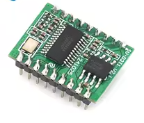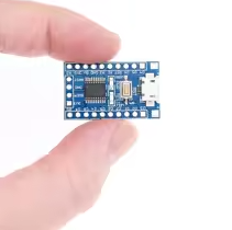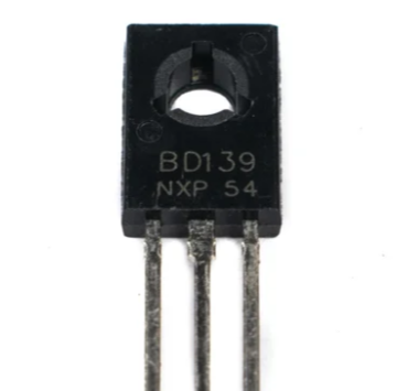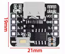
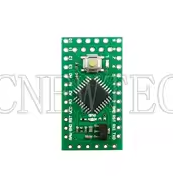
STC8G1K08A 51 MCU Development Board with ADC Function Microcontroller Controller Module
KSH 600.00
Out of Stock
The STC8G1K08A is a highspeed 1T 8051 microcontroller with builtin ADC function, ideal for compact DIY projects. Operating at 1.9V to 5.5V, it offers 6 channels of ADC input for sensor and voltage monitoring applications [citation:4][citation:7].
| Parameter | Value |
|---|---|
| Core | 1T 8051 (STC8G series) |
| Speed | Up to 12x faster than standard 8051 |
| Flash Memory | 8KB |
| Operating Voltage | 1.9V to 5.5V |
| ADC Channels | 6 (all I/O pins on 8-pin package) |
| ADC Resolution | 10-bit (configurable) |
| Package Options | SOP8, DFN8, SOP16, SOP20 |
= Key Features =
Integrated ADC 6 channels with 10bit resolution
Wide Voltage Range - 1.9V to 5.5V operation
HighSpeed Core 1T architecture for fast execution
Flexible I/O - All pins configurable as ADC inputs
Internal Reference - 1.19V bandgap for accurate measurements
No External Crystal Needed Builtin oscillator
√ Works with Keil and STC-ISP programming tools
√ Ideal for battery-powered projects
√ Widely supported by online resources
Setting up ADC on the STC8G1K08A requires careful configuration of several registers [citation:1]:
The ADC on the STC8G1K08A uses a SAR architecture that requires proper register configuration before conversion. Initialization steps include enabling ADC power, selecting the channel, and configuring timing registers [citation:1].
For multiple ADC channels:
Simple Polling Method - Wait for ADC flag to complete
Interrupt Support - ADC can trigger interrupts on completion
√ Sample code available in STC datasheets
√ Compatible with STC-ISP and Keil development tools
ADC reads zero:
ADC flag not setting:














 2.jpg "Buy AD8232 Analog Heart Rate Pulse Sensor (ECG) kit for KSH 1,500 – HIMASTORES Mombasa – Quality electronics in Mombasa, Kenya")