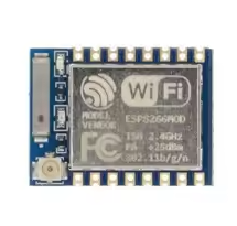
ESP-01 WiFi Module (ESP8266)
LowCost Serialto-WiFi Module for IoT Projects
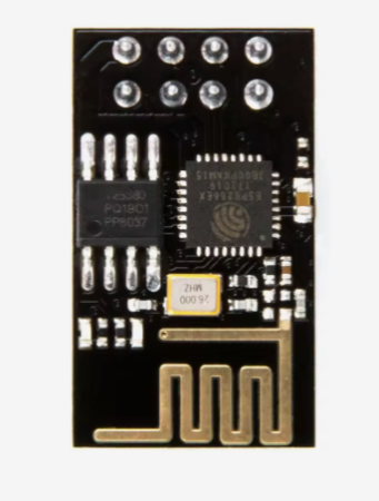
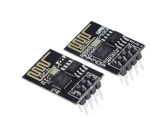
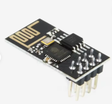
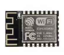
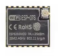
The ESP01 is a classic, ultralow-cost WiFi module based on the popular ESP8266 chip, designed to add wireless connectivity to microcontrollers like Arduino and STM32. It communicates via a simple UART interface using AT commands, making it ideal for basic IoT and remote control projects.
UltraLow Cost One of the cheapest WiFi solutions available, ideal for budget projects
Simple AT Command Control UART interface with easyto-use commands for network management
The module is 3.3V only; applying 5V will damage it permanently
Use a reliable 3.3V power supply capable of providing at least 300mA for stable operation
The default baud rate is 115200 for AT firmware
Technical Specifications
| Parameter | Value |
|---|
| Processor | ESP8266EX (Tensilica L106) |
| Clock Speed | 80MHz (up to 160MHz) |
| Flash Memory | 1MB typically |
| RAM | 32KB (user available) |
| Wi-Fi | 802.11 b/g/n (2.4GHz) |
| Interface | UART (TX/RX) and GPIO |
| Default Baud Rate | 115200 |
| Operating Voltage | 3.3V (2.5-3.6V max) |
| Peak Current | Up to 300-500mA during WiFi activity |
= Pin Configuration =
| Pin | Function | Description |
|---|
| VCC | 3.3V Power | Connect to stable 3.3V supply |
| GND | Ground | Power ground |
| TX | UART Transmit | Connect to host RX |
| RX | UART Receive | Connect to host TX |
| CH_PD/EN | Chip Enable | Must be pulled HIGH (3.3V) to operate |
| GPIO0 | Boot Selection | LOW Flash mode, HIGH Normal run |
| GPIO2 | General I/O | Limited usage, avoid pull-down at boot |
| RST | Reset | Reset module (active low) |
= Key Features =
WiFi Connectivity IEEE 802.11 b/g/n support with complete TCP/IP stack
Flexible Modes - STA (client), AP (access point), and STA+AP modes
Serial Control - Simple AT commands for configuration and data transfer
Small Form Factor DIP8 package, fits on breadboards with adapters
Community Support - Extensive tutorials and code examples available
= Applications =
- Adding WiFi to Arduino, STM32, and 51 microcontrollers
- WiFi serial data transmission (transparent transmission)
- Remote control switches and sensor data upload
- Smart home DIY projects
- Simple IoT device prototyping
Easy to Use - Requires only serial connection and AT commands
Mature Platform - Huge community support and many available firmware options
√ Can be programmed with custom firmware via serial
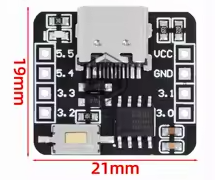
√ Compatible with most USBtoTTL adapters (3.3V)
√ Works in both Station and Access Point modes
Basic AT Command Usage
Common initialization sequence:
- AT : Test connection, responds with OK
- AT+CWMODE1 : Set to Station mode (1STA, 2AP, 3Both)
- AT+CWJAP="SSID","Password" : Connect to WiFi network
- AT+CIFSR : Get local IP address after connection
- AT+CIPSTART="TCP","IP",Port : Establish TCP connection
- AT+CIPSEND=Length : Send data of specified length
Always terminate AT commands with Carriage Return + Line Feed
AT commands are case-sensitive and must be in uppercase
GPIO0 must be HIGH for normal operation; pulling it LOW puts the module into firmware download mode
Troubleshooting
Module not responding to AT commands:
- Verify correct voltage (3.3V) and power supply current (>300mA)
- Check CH_PD/EN is pulled HIGH to 3.3V
- Confirm RX/TX connections are not swapped
- Ensure GPIO0 is HIGH (not grounded) for normal mode
Automatic reset loops:
- Check GPIO0 is not shorted to GND
- Verify GPIO2 is not pulled LOW during boot
- Ensure CH_PD/EN is stable HIGH