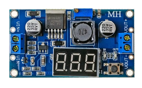
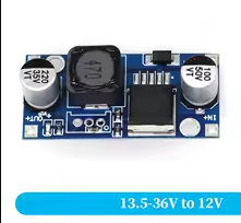
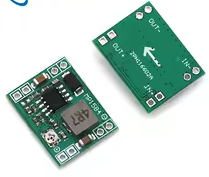
LM2596S DCDC Adjustable StepDown Power Module with LED Voltmeter
High-Power Voltage Regulator with Digital Display for DIY Projects
The LM2596S module integrates a high-efficiency buck converter with a digital LED voltmeter, offering a complete adjustable power supply solution for Arduino, ESP32, and other electronics projects.
AllinOne Solution Combines voltage regulation and realtime monitoring
High Efficiency - Up to 92% conversion with low heat generation [citation:1][citation:2]
Input voltage must be at least 1.5V higher than the desired output voltage [citation:2][citation:4]
Switch between Input and Output voltage measurement using the button
Do not exceed 40V input or 3A current rating
Technical Specifications
| Parameter | Value |
|---|
| Input Voltage | 4.0V to 40V DC [citation:1][citation:2] |
| Output Voltage | 1.25V to 37V adjustable [citation:1][citation:2] |
| Output Current | 3A max (2A continuous) [citation:1][citation:2] |
| Display Accuracy | ±0.05V [citation:3][citation:5] |
| Voltmeter Range | 0V to 40V [citation:1][citation:2] |
| Switching Frequency | 150kHz [citation:1] |
= Key Features =
Builtin LED Voltmeter Real-time voltage display with ±0.05V accuracy [citation:3][citation:6]
Dual Measurement Onebutton switch between input and output voltage [citation:1][citation:4]
Memory Function Saves display settings even after poweroff [citation:1][citation:2]
Protection Circuits - Overheat and short circuit protection [citation:1][citation:7]
Terminal Blocks - Screw terminals for easy wiring without soldering [citation:1]
= Applications =
- Arduino and ESP32 power supplies [citation:1][citation:4]
- Battery charging circuits
- LED lighting systems
- Bench power supply projects [citation:6]
- Automotive voltage regulation [citation:3]
Versatile and Powerful - Replaces multiple separate modules
UserFriendly No external meter needed for adjustment [citation:4]
√ Ready to use with included terminal blocks
√ Compact size for easy integration
√ Saves time and simplifies prototyping [citation:4]
Connection and Operation Guide
Terminal connections:
- IN+: 4.0V to 40V positive input [citation:1][citation:2]
- IN-: Input ground
- OUT+: Positive output (1.25V to 37V)
- OUT-: Output ground
Display operation:
- Right button: Switch between IN/OUT voltage display [citation:2][citation:4]
- Left button: Turn display on/off
- LED indicator shows which voltage is being measured [citation:4]
Trim potentiometer adjusts output voltage
Use a multimeter to verify output during initial setup
Ensure input voltage exceeds output by 1.5V minimum [citation:2][citation:4]
Do not exceed 3A current output
Troubleshooting
No output:
- Check input voltage is above 4V
- Verify wiring connections
- Avoid short circuits
Display shows wrong voltage:
- Press button to switch between IN/OUT measurement [citation:4]
- Check LED indicator for measurement mode
Overheating:
- Reduce load current below 2A continuous
- Add heatsink for 3A operation [citation:8]