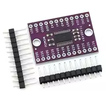
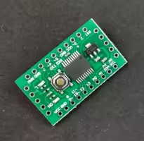
TCA9548A 8-Channel I2C Expansion Board
I2C Multiplexer Breakout Board for Arduino
The TCA9548A multiplexer expands single I2C bus into 8 independent channels, allowing multiple devices with the same address to work together on one Arduino.
8 Channel Expansion - Connect up to 8 I2C devices with same address
Hardware Resets - Individual channel control with RESET pin
Supply voltage is 1.65V to 5.5V - works with 3.3V and 5V logic
Select only one channel at a time for communication
Do not exceed 5.5V on any pin
Technical Specifications
| Parameter | Value |
|---|
| IC Type | TCA9548A |
| Number of Channels | 8 (SD0SD7 / SC0SC7) |
| Supply Voltage | 1.65V to 5.5V |
| I2C Address | 0x70 (default, adjustable) |
| Channel Selection | I2C command |
| Reset Pin | Active low |
| Interrupt Pin | Active low |
= Key Features =
8 Independent Channels - Isolated I2C buses
Level Translation - Each channel supports different voltages
Hardware Reset - Resets all channels
Interrupt Support - Channel status monitoring
Adjustable Address - Use multiple boards together
= Applications =
- Multi-sensor I2C networks
- OLED display arrays
- Multiple IMU sensor systems
- Sensor address conflict resolution
- Industrial I2C bus isolation
Solves Address Conflicts - Connect identical devices on one bus
Simple Control - Select channel via I2C commands
√ Breakout board with labeled pins
√ Ready for breadboard use
√ Great for complex sensor projects
Connection Guide
Primary side (to Arduino):
- VCC: 3.3V to 5V power
- GND: Ground
- SDA: I2C data line
- SCL: I2C clock line
- RST: Reset (optional)
- INT: Interrupt (optional)
Channel side:
- SD0-SD7: Data lines for each channel
- SC0-SC7: Clock lines for each channel
Connect pull-up resistors on each channel if needed
Use separate pull-ups for 3.3V and 5V devices
Do not enable multiple channels simultaneously
Use level translators for mixed voltage systems
Arduino Usage Example
Basic commands:
- Set channel: write to device 0x70
- Select channel 0: send 0x01
- Select channel 1: send 0x02
- Disable all channels: send 0x00
Communication sequence:
- Write channel selection byte
- Send standard I2C commands to selected device
- All other channels are isolated
Simple Programming - Standard Wire library used
Channel Selection - Single byte command
Works with all Arduino boards
Compatible with all I2C sensors
√ Pull-up resistors onboard
√ Address selectable via jumpers
√ Easy to integrate into projects
Multiple Board Setup
For multiple TCA9548A boards:
- A0, A1, A2 pins set binary address
- Default address 0x70 (all low)
- Up to 8 boards = 64 total channels
Set address before soldering
Use pull-up resistors on each channel
Each board must have unique address
Check voltage compatibility per channel
Troubleshooting
No communication:
- Check VCC and GND
- Verify I2C connections
- Avoid loose connections
Device not found on channel:
- Select correct channel
- Verify power to device
- Use level shifting if needed