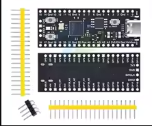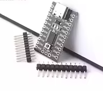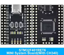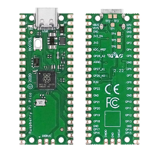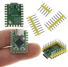
Raspberry Pi pico mini RP2040-Zero Microcontroller Development Board RP2040 Dual Core Processor
KSH 1,000.00
Out of Stock
The RP2040Zero is a mini development board based on the official Raspberry Pi RP2040 dualcore processor. It offers high performance in a compact form factor, ideal for wearable tech, IoT devices, and embedded systems [citation:1][citation:5].
| Parameter | Value |
|---|---|
| Processor | RP2040 Dual-Core Arm Cortex M0+ [citation:1] |
| Clock Speed | Up to 133 MHz [citation:2] |
| Flash Memory | 2MB [citation:5] |
| SRAM | 264KB [citation:3] |
| GPIO Pins | 29 (20 via pin headers) [citation:12] |
| ADC Channels | 4 x 12-bit [citation:3] |
| PWM Channels | 16 [citation:5] |
| Interfaces | 2x SPI, 2x I2C, 2x UART [citation:1] |
= Key Features =
USBC Connector Modern port for programming and power [citation:5]
Programmable I/O (PIO) - 8 state machines for custom peripherals [citation:1]
DragandDrop Programming - Copy UF2 files via USB mass storage [citation:2]
WS2812 RGB LED Builtin NeoPixel for status indication [citation:3]
LowPower Modes Sleep and dormant modes for battery projects [citation:6]
Temperature Sensor Onchip sensor for environmental monitoring [citation:1]
√ Supports MicroPython, C/C++, and Arduino IDE [citation:4]
√ BOOT and RESET buttons onboard [citation:5]
√ Type-C port for easy connection
Key pins:
No USB connection:
LED not working: