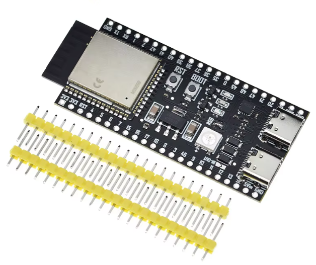
ESP32-S3-DevKitC-1
KSH 1,500.00
In Stock
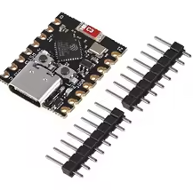
The ESP32S3DevKitC1 is an entrylevel development board equipped with ESP32S3WROOM1, ESP32S3WROOM1U, or ESP32S3WROOM2 modules, providing a generalpurpose Wi-Fi + Bluetooth LE MCU platform [citation:1]. Most I/O pins are broken out to pin headers on both sides for easy interfacing with peripherals or breadboard mounting [citation:1][citation:3].
| Component | Description |
|---|---|
| ESP32S3WROOM-1/1U/2 | Wi-Fi + Bluetooth LE MCU module with PCB antenna (1/2) or external antenna connector (1U) [citation:3][citation:5] |
| USBtoUART Port | Micro-USB port for power, flashing, and serial communication [citation:1] |
| Native USB Port | Full-speed USB OTG interface for programming, power, and JTAG debugging [citation:1][citation:3] |
| Boot Button | Hold while pressing Reset to enter Firmware Download mode [citation:1] |
| RGB LED | Addressable RGB LED (GPIO38 on v1.1, GPIO48 on v1.0) [citation:7][citation:11] |
| 5V to 3.3V LDO | Power regulator converting 5V input to 3.3V output [citation:1] |
= Ordering Variants =
| Ordering Code | Module | Flash | PSRAM |
|---|---|---|---|
| N8R8 | ESP32S3WROOM1N8R8 | 8MB QD | 8MB OT |
| N32R16V | ESP32S3WROOM2N32R16V | 32MB OT | 16MB OT |
| 1U-N8R8 | ESP32S3WROOM1UN8R8 | 8MB QD | 8MB OT |
= Key Features =
+Power Supply Options USBto-UART port, native USB port, or 5V/3.3V pins [citation:1][citation:7]
Bootloader Support - Hold Boot Reset for firmware download mode [citation:1][citation:3]
+USBtoUART Bridge - Up to 3 Mbps transfer rate for fast programming [citation:1][citation:3]
+Addressable RGB LED - Onboard indicator driven by GPIO38/48 [citation:1][citation:7]
+All Pins Broken Out - Most GPIO pins available on side headers except SPI flash/PSRAM pins [citation:1][citation:3]
√ Compatible with ESPIDF v4.4+ and ArduinoESP32
√ Onboard USBtoUART for easy programming
√ Available with multiple Flash/PSRAM configurations
Board not detected:
Programming fails: